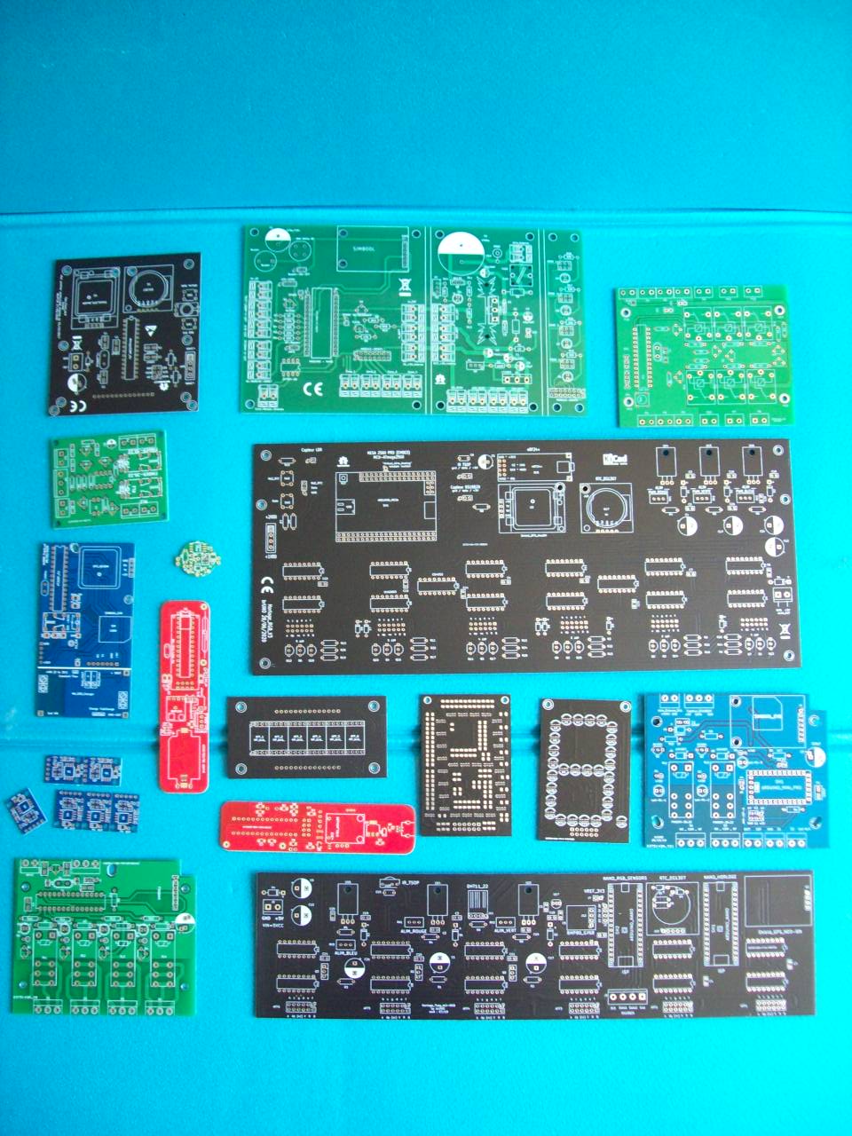
This was supposed to be a relaxing hobby, and instead I was just getting angry with ridiculous design decisions and obnoxious bugs. I always wanted to get more into electronics but I knew tools were crap so I was putting it aside but last year I finally started tinkering with electronics and so naturally I tried all the electronics simulators and design tools in Ubuntu repository. # Note: a more generic approach is to use 'copper' but then the filenamesĬomment: Drill files compatible with JLCPCBĬomment: "Pick and place file, JLCPCB style" # Gerber and drill files for JLCPCB, without stencilĬomment: 'Only parts with JLC (LCSC) code'Ĭomment: 'Just a place holder for the rotation filter'

Only parts with LCSC column are exported in the JLCPCB BOMs. When adding components, add "LCSC" to overall schematic (BOM export will fail if added to each part separately (join issue)) and the part number in each part in order to use the JLCPCB assembly service. I gathered my setup from a few sources but the main one is and. Consequently, you have to swing the angles to weird things like multiples of 7 or 13 degrees to prevent that. If traces are small enough that they fit between the PCB weave, different traces can have enough difference in electrical permittivity that it will screw up the matching (trace 1 has an FR-4 fiber directly underneath while trace 2 only has cross fibers underneath and so has about 50% air underneath instead of 100% fiberglass). In fact, the only good argument for using non-Euclidean traces is in the ultra-high-speed arena (think DDR4 bus or multi-GHz RF). All for effectively no benefit on 99.9% of all PCB designs. You have to operate control points for every single segment rather than just dragging a trace. Ever tried to manipulate font outlines? It's like that on a PCB, only an order of magnitude worse. Curved traces make your GUI ridiculously unmanageable.

Aside high frequency busses (which you're doing EM analysis on anyways), traces can be all sorts of shapes. Well, to be fair, the 0/45/90 deg traces are a byproduct from early days of EDA CAD products.


 0 kommentar(er)
